EE579 Wireless and Mobile Networks Design and Laboratory Course Project
Designed by YiHsin Weng, Hyuntae Kim and Yongqiang Li
Instructed by Professor Bhaskar Krishnamachari
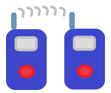
It would be very fantastic experiences and very practical needs to communicate other peers in a secure manner with off-the-shelf devices without any access point or internet. This direct communication between two mobile devices does not rely on any infrastructures and has very low cost and very fast preparation to begin this direct wireless communication. There are many circumstances or scenarios which need this direct peer-to-peer wireless communication. In the battlefield, a squad of soldiers is executing a special mission i.e. to destroy the enemy's radio station. How to address the communication issue among the members of this squad of soldiers is a very critical issue. In mountaineering expeditions a team of members are separate with each other; there is no wireless network, no internet. How to solve the communication issue among the team members is a very significant contribution. In our daily life there are some other scenarios which need this wireless direct communication. In a large company or the campus of a university employees communicated with each other very frequently. The phone bill or internet bill payment is a large amount of budget or cost. How to reduce the phone call fee or internet data flow usage fee is a big issue. In a fire site where the large building was fired without any access point or internet how stranded people communicate with the people outside is a very emergent issue. Not only for the fire site, all stranded people caused by the disaster, i.e. fire, earthquake, Tsunami, volcanoes and Debris flow, need to communicate with the outside in a very emergent way while the regular communication facilities are destroyed, such as phone facilities or internet facilities. How to handle this SOS communication in these emergent circumstances are very critical. The solution to address all these needs is wireless direct communication of Walkie-Talkie in this report. This direct communication of Walkie-Talkie allows two or more peers to talk to other ones directly by using mobile devices.
In order to meet all those needs requiring Walkie-Talkie we designed and specified some goals or principles to design the wireless direct communication framework. First of all, this direct mobile communication does not rely on access point. Second of all, this direct mobile communication is wireless. Third of all, this direct mobile communication is low latency, meaning that the talk is responded very quickly. Fourth of all, this direct mobile communication is high bandwidth, meaning that there is no congestion and audio is very smooth. We summarized these design goals or principles to be ad-hoc, wireless and real-time. To implement these design principles we choose to implement our walkie-talkie in android mobile devices on top of Wifi-Direct.

Figure 1. Walkie-Talkie Architecture
Our main goal is to use WiFi-Direct and Audio realtime recording/playing to setup a communication between android devices which are in the same group frequency ID. Therefore, our Walkie-Talkie architecture has to handle WiFi-Direct communication, Audio Recorder/Player and Group Frequency Exchanging/Maintainance. In order to achieve our goal, we divided our Walkie-Talkie architecture into three layers: WiFi-Direct Layer, Walkie-Talkie Layer and Manager Layer.
The WiFi-Direct Layer is used to handle the WiFi-Direct communication including discovering peers, connecting peers and maintaining WiFi-Direct connection status. Inside this WiFi-Direct Layer, there is a WifiBroadcastReceiver object; this object will help to monitor any event changing and inform our Walkie-Talkie Layer.
The Walkie-Talkie Function Layer helps to handle the user interface and audio communication between peers. Once the Walkie-Talkie application is turned on, it will generate a signal to inform WiFi-Diret layer to discover and connect peers. Moreover, there is a peer-device-list object which is used to maintain available peers and store the peer information in the database. If WiFi-Direct layer has discovered some peers, the WiFi-Direct layer will generate peer list information and pass this information to the Walkie-Talkie layer.
The Manager Layer has two main functions: Node Manager and Frequency Manager. For the function of Node Manager, it helps to construct sockets that send/receive audio and beacon messages to/from peers. The Frequency Manager contains a frequency map which is used to decide whom it should send message to. In our Walkie-Talkie application on the android phone, user can only talk to another device if they have same virtual frequency. This behavior is like the real Walkie-Talkie device that uses the frequency to modulate the audio message. The receiver needs to know the frequency to hear the audio message. Therefore, in our Walkie-Talkie, we introduce this virtual frequency as a talk group ID that the audio message can only transmit and receive if they are in the same group.
As shown in bellow figure, A, C and D has same virtual frequency. Therefore, A, C and D can talk to each other. B has different virtual frequency. This means that B is not in the communication group. When any device is speaking, our Walkie-Talkie application will only forward the audio message to those devices with same frequency ID.
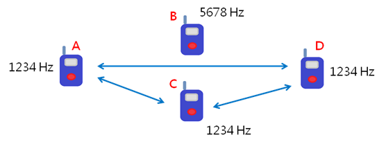
Figure 2. Walkie-Talkie frequency, devices with same frequency can talk to each other
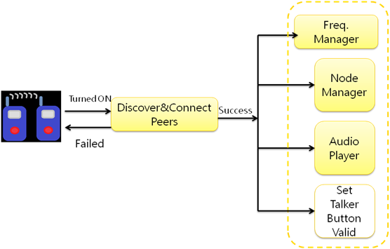
Figure 3. Walkie-Talkie Flow-Chart 1
The flow chart shows how our Walkie-Talkie works when the user turns on the application. First of all, when the Walkie-Talkie on/off button is turned on, the WiFi-Direct will start to discover peers and connect to peers. After successfully connecting, the Walkie-Talkie will create three objects: Frequency Manager, Node Manager and Audio Player. Moreover, it will set the talker button valid to let user can start to talk to each other. The next figure shows more details about these three objects.
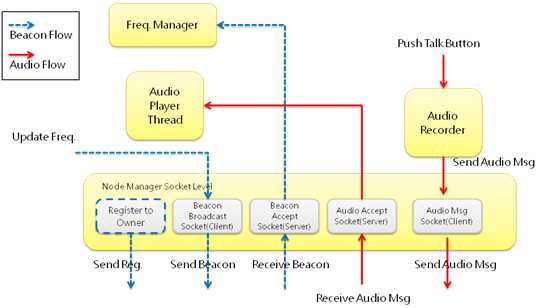
Figure 4. Walkie-Talkie Flow-Chart 2
In our Walkie-Talkie, after connection is set up, we will have two kinds of flows: Beacon Flow (control message) and Audio Flow (audio message) to handle exchange information between devices. First of all, when a WiFi-Direct group is formed, due to the behavior of WiFi-Direct, each WiFi-Direct group has a group owner and rests of devices are group members. All devices in the group only know the group owner's IP address. This means that in the beginning they can only send data to the group owner. Therefore, we create two steps registration mechanism to handle this issue. If the device is not a group owner, it must registers its' IP address to the group owner. After that the group owner can help to disseminate members' address to other devices. The bellow figure shows that when the WiFi-Direct group is formed, A is the group owner and B/C is the group member. At step 1, B/C needs to register to A to let A obtain the IP address of B/C. At step 2, A will generate a control message and send to B/C to help B/C obtain the IP address of group members.
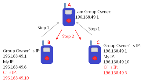
Figure 5. Walkie-Talkie registration steps
For the Beacon Flow, the Beacon Broadcast Socket (Client) will keep broadcast the control message which including the IP address and the virtual frequency. If the user updates the virtual frequency, this broadcast socket will help to send new beacon message to peers immediately. The Beacon Accept Socket (Server) helps to receive beacon messages, extract the frequency information and inform the received frequency to upper layer. The bellow figure shows that the frequency of A/C/D is 1234Hz and the frequency of B is 5678Hz. After the beacon exchanging, each device will receive the control message from each other. Therefore, the Frequency Manager will generate a table to maintain the frequency of peers.
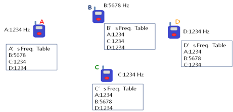
Figure 6. Walkie-Talkie frequncy table
The second type of flow is Audio Flow which handles audio communication messages. When the Walkie-Talkie is turned on, the Audio-Player Thread is created and is run in the background. After received audio message, the Audio Accept Socket will send the audio message to the Audio-Player Thread. Therefore, the user can hear the voice played by the Audio-Player Thread. If the user pushes the talk button, the Audio Recorder object will be created to record voice and send audio message to down layer. The down layer Audio Msg Socket will create sockets and send out the audio message to those devices in the same frequency group.

Control Packet contains three fields: Source Device, Type and Message field.

Even we are going to implement walkie-talkie feature thru wifi-direct in android devices. Our goal is to achieve to realize the real-time talking among peers. This real time talk is very similar to a phone call.
Even android does not explicitly explain how the audio recording and audio playing back work. Still We tracked how the audio architecture is from the clues mentioned in audio SDK and openSL ES NDK. The related audio queue architecture explanation can be found in [1]. We believe the Android audio architecture is very similar to the Mac one. Maybe this similarity is why Android does not mention what its audio queue architecture is. As mentioned in [1] an audio queue has the following responsibilities:
Since audio queue is connected to audio hardware and mediating recording or playback. Therefore the effectiveness of audio queue depends on the hardware.
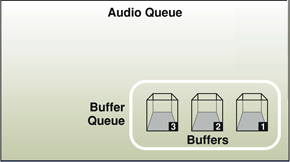
Figure 7. Audio Queue illustration, adapted from [1]
Every audio queue has virtually the same common data structure, containing three key elements:
The audio data structure in Figure 7 is employed both in audio recording and audio playback.
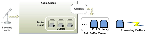
Figure 8. Illustration of Audio Queue for Recording, adapted from [1]
As shown in Figure 8, the incoming audio is acquired by a microphone. And the incoming audio is stored and maintained by an audio queue. Figure 9 shows how the process audio recording works.
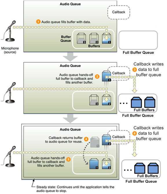
Figure 9. The process how the audio recording works, adapted from [1]
Audio Queue fills or feeds the incoming audio into Buffers in the Buffer Queue of the recorder. When a buffer if fully charged or filled, the callback is triggered, and this full buffer is polled or popped out of the Buffer queue to be read to our walkie-talkie application. At the same time another buffer is pushed to the head of the buffer queue of recorder to begin to be filled or charged. Once the previous full buffer is read to the walkie-talkie and become empty, this empty buffer is returned to the Buffer Queue and pushed to the end of the audio buffer queue to be recharged or filled again.
In our walkie-talkie, we use our own audio queue to store the full buffers read from the audio Buffer queue of recorder. The reason why we use our own audio queue to store the audio buffer instead of forwarding this buffer directly is the latency issue. If the latency to forward a buffer to the destination was too high, the empty buffer would not be return to the buffer queue to be recharged in time. Then the quality of audio recording would be influenced.
In real time, the full buffer in our walkie-talkie queue is forwarded to the destination through our protocol on top of wifi-direct sockets. Buffer size depends on the sampling rate and different android devices. In our walkie-talkie we used sampling rate with 8000 for the buffer recording.
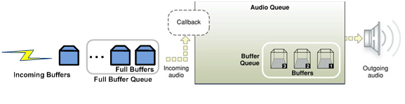
Figure 10. Illustration of Audio Queue for Playback, adapted from [1]
As shown in Figure 10, the outgoing audio is entering the loudspeaker. The incoming audio full buffers are being received from the sender by using protocol on top of wifi-direct. And the incoming audio is stored and maintained by an audio queue. However, the callback mechanism is on the left side of Audio Queue different from the right side of Audio Queue in Audio Recording. Figure 11 shows how the process audio playback works.
These incoming audio full buffers are stored in our own audio buffer queue in walkie-talkie. The reason to employ our own full buffer queue is to eliminate the non synchronization of the incoming data and the outgoing data. The buffer in our own audio buffer queue is written into the buffer in the audio queue of the audio player. This writing process is controlled by a callback mechanism.
When the buffer is empty in the Audio Queue, it triggers callback to read data from our walkie-talkie audio buffer queue. Once the buffer is fully filled or charged this full buffer is pushed into the buffer queue of the audio player to be lined up to be played. As soon as the full buffer finishes its playing, this empty buffer is popped out and triggers another callback to write audio data from our walkie-talkie buffer queue. Simultaneously the full buffer in the second place is pushed to the head of the buffer queue to be playing.
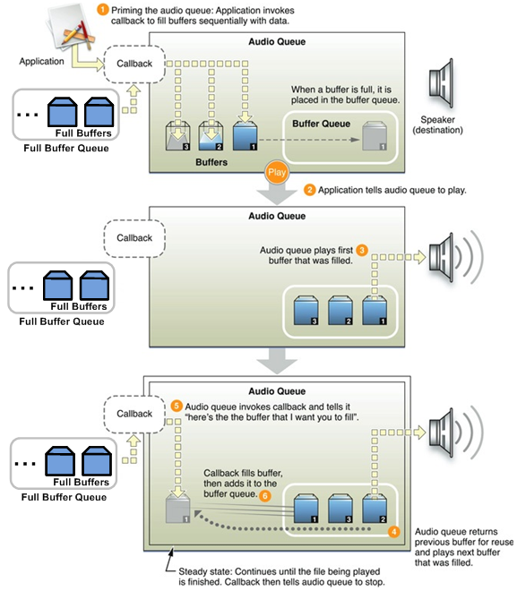
Figure 11. The process how the audio playback works, adapted from [1]
Buffer size depends on the sampling rate and different android devices. In our walkie-talkie we used sampling rate with 8000 for playback which is the same as the audio recording.
In android, only 16 bit audio data is supported. And 8 bit audio data is not supported. The incoming audio data is recorded as pulse code modulation (PCM). Both audio recording and audio playback only supports PCM format of audio data. We have finished some codec work to encode the PCM data from audio recording and decode it before it is being playing to playback. We used mulaw [2,3] to implement this encode and decode of PCM audio data. However, these decoded audio data from encoded audio data turn out to be a series of noise sound. From the responsibility of the audio queue we believe the audio queue in audio recording has already encoded the PCM data. In another word, the PCM data read from the callback of the audio queue of the audio recording is 8 bit encoded PCM. Similarly after this encoded 8 bit PCM data is written into the callback of the audio queue of the audio playback is decoded into 16 bit PCM before it is playing. During our debugging we observed that the minimal buffer size of the playback is twice as long as that of the audio recording. Since the encoded audio PCM is 8bit, and the decoded audio PCM is 16 bit. Therefore the decoded audio PCM is twice long as the encoded audio PCM data. It is possible that this codecs can explain why the minimal buffer size of the playback is twice as long as that of the audio recording. The player for playback in our real-time walkie-talkie only supports wav format of audio data to play the incoming stream of PCM data.
Since the sound wave is reflected from the obstacles, walls or buildings. Therefore there exists echo. When two walkie-talkie phones are very close to each other for the playing audio is recorded again, the echo issue is more serious. However this case rarely happens in our real life. We addressed this echo issue partially. When the talker finishes his/her talking, an "end" message is sent to the listeners. Then the listener won't receive echo audio any more. For those echoes during the talking, we do not fix it since the current performance or quality can be accepted to some extent now. We plan to fix this type of echo in the future.
The test results show that our Walkie-Talkie application framework on top of Wi-Fi Direct works very well. It works within 20 to 30 meters in the isles in RTH building. This Walkie-Talkie application achieves the goal to communicate among peers in an ad-hoc wireless network. In addition the audio recording and playback have been experimented to work well in real time. The echo issue is an issue in our real time Walkie-Talkie application.
Our Walkie-Talkie project was finished under the guide of Professor Bhaskar Krishnamachari and under the assistance of TA Maheswaran Sathiamoorthy. Without the insightful guide of Professor Bhaskar Krishnamachari and the dedicated assistance of TA Maheswaran Sathiamoorthy it is impossible for us to finish this project.