Difference between revisions of "RPL Border Router"
(→Code building blocks.) |
(→Introduction:) |
||
| Line 9: | Line 9: | ||
1. Understanding the working of the rpl border router code <br> | 1. Understanding the working of the rpl border router code <br> | ||
2. Starting a simulation on Cooja simulator. <br> | 2. Starting a simulation on Cooja simulator. <br> | ||
| − | 3. Observing the results <br> | + | 3. Observing and validating the results <br> |
== Code building blocks. == | == Code building blocks. == | ||
Revision as of 14:58, 8 November 2014
Contents
Introduction:
Border routers are routers that can be found at the edge of a network. Their function is to connect one network to another. In this tutorial we will learn how to run a simulation using the border router in Contiki In the example which we will discuss in the rest of this tutorial the border router will be used to route data between a WSN (using RPL) and an external IP network. Objective: The objective of this tutorial is to give you an understanding of the RPL Border Router code on Contiki OS and learn how to simulate the code on Cooja What will you learn at the end of this tutorial. At the end of the tutorial you would have learnt the following:
1. Understanding the working of the rpl border router code
2. Starting a simulation on Cooja simulator.
3. Observing and validating the results
Code building blocks.
We will using the following files
1. border-router.c
2. udp-server.c (udp-client.c can also be used)
3. slip-bridge.c
4. httpd-simple.c
udp-server nodes will form a DAG with the border router set as the root. The border router will receive the prefix through a SLIP connection and it will be communicated to the rest of the nodes in the RPL network.
Refer to the following code snippets in the file border-router.c In this piece of code the node configured as the border router waits for the prefix to be set. Once it receives the prefix, the border router is set as the root of the DODAG after which it sets the prefix of the rest of the nodes in the network.
/* Request prefix until it has been received */
 while(!prefix_set) {
   etimer_set(&et, CLOCK_SECOND);
   request_prefix();
   PROCESS_WAIT_EVENT_UNTIL(etimer_expired(&et));
 }


 dag = rpl_set_root(RPL_DEFAULT_INSTANCE,(uip_ip6addr_t *)dag_id);
 if(dag != NULL) {
   rpl_set_prefix(dag, &prefix, 64);
   PRINTF("created a new RPL dag\n");
 }
Compiling the code
The code for RPL border router can be found at /contiki-2.7/examples/ipv6/rpl-border-router. Use the following command to compile the code for the border router
cd /contiki-2.7/examples/ipv6/rpl-border-router
make TARGET=sky.
Once this command has been successfully executed a file named border-router.sky will be created. This file will be used to program one of the motes as the border router on Cooja. For the purpose of this tutorial we will select TMote Sky as our target.
In order to demonstrate the functioning of the border router we will create a network of nodes with the border router as the root. For creating such a network we will user the udp-server.c code. This code can be found at /contiki-2.7/examples/ipv6/rpl-udp . Use the following command to compile the code for rpl-udp
cd /contiki-2.7/examples/ipv6/rpl-udp
make TARGET=sky
Once this command has been successfully executed a file named udp-server.sky will be created. This file will be used to program the remaining nodes in Cooja simulator. These nodes will form a DAG with the rpl border router as the root.
Testing on Cooja
Upon the successful completion of the above mentioned steps we are ready to create a simulation in Cooja. Start the Cooja simulator using the following command
cd /contiki-2.7/tools/cooja
ant run
When the GUI launches execute the following steps to create a simulation.
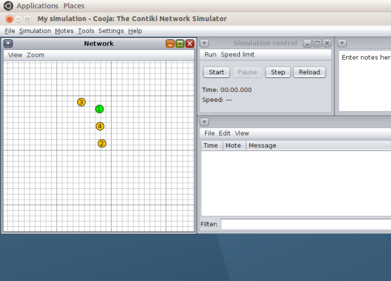
1. From 'File' select 'New Simulation'. Select UDGM, enter the name of the simulation and click on create.
2. Click on Motes. From the drop down menu select 'Add New Motes' followed by 'Create new motes' and select the mote type as Sky.
3. Browse to the location /contiki-2.7/examples/ipv6/rpl-border-router and select the file rpl-border-router.sky. Click on 'Create'. Add one mote of this type.
4. Repeat step 2 and 3 but this time browse to the location /contiki-2.7/examples/ipv6/rpl-udp and select the file udp-server.sky. Add 3 - 4 motes of the type udp-server
5. Once the motes have been added you can position the motes.
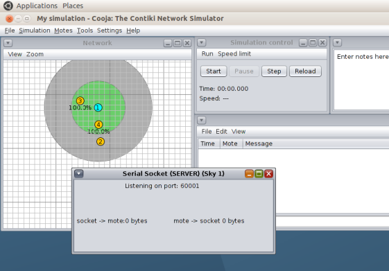
6. Now, we need to create a bridge between the RPL network simulated on Cooja and the local machine. This can be done by right clicking on the mote which is programmed as the border router. Select 'More tools for border router' and then select 'Serial Socket (SERVER)'. You will get the following message on the successful completion of this step.Note that the message says 'Listening on port 60001'
7. Now start the simulation by clicking on Start
Tunslip utility
As mentioned in the introduction a border router helps in connecting one network to another. In this example the border router is used to route data between an RPL network and an external network. Till now we have only created the RPL network. Now we need to simulate the scenario in which this RPL network is connected to an external network. For this purpose we will use the Tunslip utility provided in Contiki. In this example tunslip creates a bridge between the RPL network and the local machine. tunslip6.c can be found in /contiki-2.7/tools Compile the tunslip6 code.
make tunslip6
Make a connection between the RPL network and your local machine.
sudo ./tunslip6 -a 127.0.0.1 aaaa::1/64
On the successful execution this command the following output will be printed on the terminal.
slip connected to ``127.0.0.1:60001''
opened tun device ``/dev/tun0''
ifconfig tun0 inet `hostname` up
ifconfig tun0 add aaaa::1/64
ifconfig tun0 add fe80::0:0:0:1/64
ifconfig tun0

tun0      Link encap:UNSPEC  HWaddr 00-00-00-00-00-00-00-00-00-00-00-00-00-00-00-00
          inet addr:127.0.1.1  P-t-P:127.0.1.1  Mask:255.255.255.255
          inet6 addr: fe80::1/64 Scope:Link
          inet6 addr: aaaa::1/64 Scope:Global
          UP POINTOPOINT RUNNING NOARP MULTICAST  MTU:1500  Metric:1
          RX packets:0 errors:0 dropped:0 overruns:0 frame:0
          TX packets:0 errors:0 dropped:0 overruns:0 carrier:0
          collisions:0 txqueuelen:500
          RX bytes:0 (0.0 B)  TX bytes:0 (0.0 B)

Rime started with address 0.18.116.1.0.1.1.1
MAC 00:12:74:01:00:01:01:01 Contiki 2.7 started. Node id is set to 1.
CSMA ContikiMAC, channel check rate 8 Hz, radio channel 26
Tentative link-local IPv6 address fe80:0000:0000:0000:0212:7401:0001:0101
Starting 'Border router process' 'Web server'
*** Address:aaaa::1 => aaaa:0000:0000:0000
Got configuration message of type P
Setting prefix aaaa::
Server IPv6 addresses:
 aaaa::212:7401:1:101
 fe80::212:7401:1:101
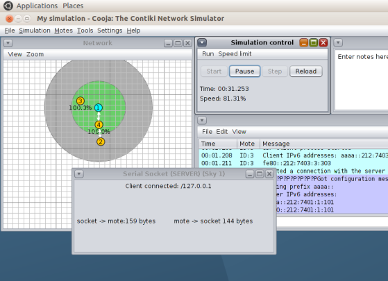
Go back to the Cooja simulator GUI and look at the dialogue box. The message has now changed to 'Client connected: /127.0.0.1'
Verifying Results
You can verify that the address of the border router has been set by using the ping command.
user@instant-contiki:~/contiki-2.7$ ping6 aaaa::212:7401:1:101
PING aaaa::212:7401:1:101(aaaa::212:7401:1:101) 56 data bytes
64 bytes from aaaa::212:7401:1:101: icmp_seq=1 ttl=64 time=86.0 ms
64 bytes from aaaa::212:7401:1:101: icmp_seq=2 ttl=64 time=33.6 ms
64 bytes from aaaa::212:7401:1:101: icmp_seq=3 ttl=64 time=82.3 ms
64 bytes from aaaa::212:7401:1:101: icmp_seq=4 ttl=64 time=43.3 ms
64 bytes from aaaa::212:7401:1:101: icmp_seq=5 ttl=64 time=70.1 ms
^C
--- aaaa::212:7401:1:101 ping statistics ---
5 packets transmitted, 5 received, 0% packet loss, time 4006ms
rtt min/avg/max/mdev = 33.669/63.090/86.015/20.985 ms
You can also ping one of the other nodes in the network. Here we are pinging node 4
 user@instant-contiki:~/contiki-2.7$ ping6 aaaa::212:7404:4:404
PING aaaa::212:7404:4:404(aaaa::212:7404:4:404) 56 data bytes
64 bytes from aaaa::212:7404:4:404: icmp_seq=1 ttl=63 time=670 ms
64 bytes from aaaa::212:7404:4:404: icmp_seq=2 ttl=63 time=703 ms
64 bytes from aaaa::212:7404:4:404: icmp_seq=3 ttl=63 time=746 ms
64 bytes from aaaa::212:7404:4:404: icmp_seq=4 ttl=63 time=674 ms
^C
--- aaaa::212:7404:4:404 ping statistics ---
5 packets transmitted, 4 received, 20% packet loss, time 4001ms
rtt min/avg/max/mdev = 670.230/698.666/746.619/30.514 ms
user@instant-contiki:~/contiki-2.7$
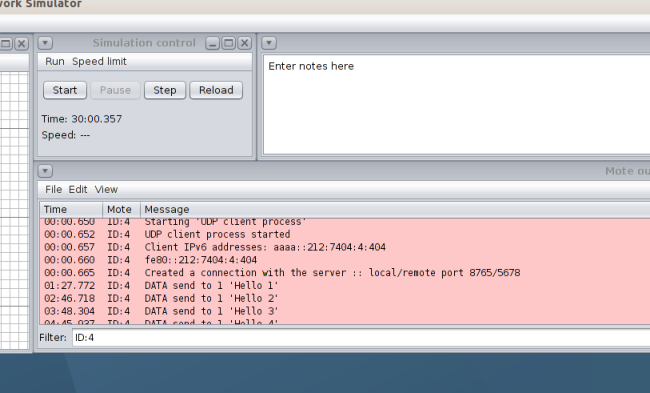
The IPv6 address of a node can be checked from the log screen on Cooja. Filter the nodes by their ID
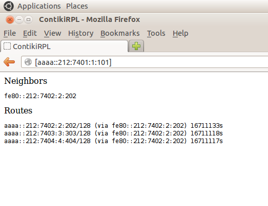
You can enter the address of the border router in the web browser. The border router host a page which will be displayed on the browser as shown below.
Common Issues
1. Make sure that you enter the IPv6 address properly in the command sudo ./tunslip6 -a 127.0.0.1 aaaa::1/64 . There should be no spaces in aaaa::1/64. Otherwise the code will give unexpected behavior.
2. When you pause the simulation the SLIP connection is lost. It might not work properly on resuming the simulation. In such cases reload the simulation. Create a fresh SLIP connection and then run the simulation again.
References
[1] https://github.com/njh/contiki/blob/master/cpu/mc1322x/doc/rpl-tutorial.md
[2] Using the Contiki Cooja Simulator - Anuj Sehgal
